

ASSESSMENT OF QUEEN'S HIGHWAY
In accordance with the Road Traffic and Speed Limit (Eleuthera) Regulations – Section 43(2) the Queens Highways is posted at 45 mph for motor vehicles other than omnibuses having a seating capacity for more than 20 passengers or, trucks for which the speed limit shall be 30 mph.
The existing Queens Highway, on the approaches to the existing bridge, are constructed of a combination of a double seal treatment wearing surface (pea-rock base & sand seal surface) and concrete pavement surface. In the overtopping areas, concrete spillways have been constructed on the Bight side to convey the water and to try and prevent side slope erosion resulting from this action. The condition of the wearing surface is fair to poor with frequent ruts and potholes and uneven roadway crossfall throughout the limits of the bridge replacement
project.
Field measurements of lane widths on the existing roadway approaches on the Queens Highway range from 9 to 10 feet. AASHTO recommends a minimum 10-foot lane for Low-Speed types of roadway facilities and 11-foot lanes only for Rural Arterial roads. Whereas the Ministry recommends 10-foot lanes with a 3% cross slope and 2-foot shoulder for all roadways on the Family Islands. A detailed assessment of the Queens Highway with various Design Speeds (55 mph, 40 mph and 30 mph) can be found in the Final Roadway Design Criteria Report, (referto Appendix A) which references both American Association of State Highway Transportation Officials (AASHTO) and Ministry roadway design guidelines. AASHTO is the engineering standard used in North America for highway design and construction.
The AASHTO publication – A Policy on Geometric Design of Highways and Street 7th Edition 2018 defines the three categories of design speed as follows:
1. High Speed Design speeds of 50 mph and greater
2. Low Speed Design speeds of 45 mph and less
3. Very Low Speed Design speeds of 35 mph and less
An analysis of the existing Queens Highway (horizontal and vertical alignments) on the roadway approaches to the existing bridge was completed (best fit alignments). This analysis indicates that in general the highway achieves the necessary horizontal curvature (using AASHTO criteria) for the posted speed of 45 mph except for the sharp curve immediately north of the north bridge abutment, which is further compounded by a rock face that results in a blind corner (line of sight issue). The vertical alignment, in many locations, does not achieve the necessary vertical curvature (using AASHTO criteria) and exceeds the recommended longitudinal grade for the posted speed limit (based upon AASHTO standards). The Bahamian standard (Design and Construction Guidelines - 2004) recommends the longitudinal grade not exceed a maximum slope of 8.3%, regardless of the posted speed limit. Reducing the posted speed to 30 mph greatly improves sight distances on the approaches to the bridge, for both stopping sight distance and headline sight distance. Refer to Appendix B for an assessment of the Queens Highway (horizontal and vertical alignments) based upon the current posted speed
of 45 mph and the recommended posted speed of 30 mph.
Existing roadside safety is accomplished through a combination of Guardrail on the Bight side south of the bridge and a Gravity Wall with curbing and Guardrail north of the bridge.
The roadway shoulder area is generally constructed of either a double seal treatment or concrete (durable surface) due to the constant overtopping, which has resulted in an almost total lack of vegetation (ground cover), leaving the adjacent land to be of exposed limestone rock.
While the Ministry has maintained these roadway approaches, the constant overtopping has resulted in both
roadway degradation and concrete spillway failures as evident by slabs of broken concrete adjacent to the
roadway.
The areas of saltwater runoff, overtopping and spray, as developed by Cummins Cederberg Coastal & Marine Engineering, are shown in Figure 3 to Figure 6 below. From this depiction it is very evident that these conditions at the existing bridge and highway approaches result in an extremely aggressive environment.

Figure 3 - Areas of saltwater runoff, overtopping, and spray

Figure 4 - South bridge approach looking north

Figure 5 - North bridge approach looking south

Figure 6 - Failure of concrete spillage on Northside of the bridge
On the south side of the bridge approach there appears to be a concrete patch completed in the immediate vicinity of a large cavity beneath the roadway (Figure 7). This cavity (documented through drone footage as shown in Figure 8) potentially extends considerably beneath the Highway alignment and future failures are likely to occur. To further qualify the extent of this cavity, an active blowhole is located on the west side of the Highway (Bight side) at approximately 20-feet from the edge of the roadway (suggesting the cavity extends this far if not more beneath the Highway).

Figure 7 - Concrete patch in large cavity area

Figure 8 - Large cavity beneath the Queens Highway
EXISTING UTILITIES
The existing bridge conveys a 10” potable watermain providing a vital connection (as there is no redundancy) between the communities on the north and south parts of the island. The Polyvinyl Chloride (PVC) pipe has not been protected from the elements (UV light) and shows the impact that UV degradation has on unprotected PVC pipe (Figure 10). In addition to the PVC, the potable water main is also constructed of concrete pressure pipe (Figure 11), exposed on the bridge (but protected from the adjacent traffic).

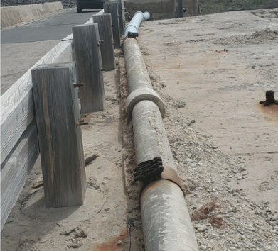
Figure 10 - Existing 10" PVC waterman
Figure 11 - Existing 10" concrete waterman
On the roadway approaches to the existing bridge the watermain is partially buried but the pipe is also laid on the surface. Generally, the watermain is protected by either a concrete barrier wall or guardrail (Figure 12) although one short section within the project limits as shown in Figure 13 is not protected from the adjacent vehicular traffic (this is not desirable as an errant vehicle could disrupt the potable water supply until emergency repairs are made and assuming the materials required for such a repair are on the island).

Figure 12 - Protected Surface Watermain

Figure 13 - Unprotected Surface Watermain
Both power and telecom lines are pole mounted on wooden utility poles on both roadway approaches to the bridge. Photographic evidence suggests that some of telecom cables do not span the existing bridge but are buried beneath the water on the Bight side (Figure 14).
The approximate length of this telecom diversion is approximately 1000-feet north of the existing bridge and resurfaces near the blowhole on the south side of the bridge. From the photograph below, the cable is protected by PVC pipe however, there is no evidence of armoring (rock protection of the PVC pipe from boat anchors).

Figure 14 - Buried Cable (Bight Side)
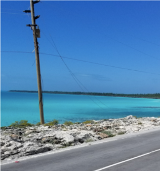
Figure 15 - Evidence of discontinuing aerial cable
CONCEPTS OPTIONS DEVELOPMENT & ANALYSIS
During preliminary design, it was determined that the bridge would accommodate two 12 ft lanes of traffic, one in each direction, a 6 ft shoulder and a solid concrete barrier 1 ft 6 in thick on the Bight side and an 8 in thick raised sidewalk, 6 ft in width, with a 111⁄4 in thick solid concrete parapet wall with steel railing on the Atlantic Ocean side. During detailed design, the cross section was optimized, as shown in Figure 16, to accommodate two 11 ft lanes of traffic, a 4 ft shoulder and 1 ft 6 in concrete barrier on the Bight side, a 1 ft 4in offset with a 9.5 in thick, 6 ft wide sidewalk and a 13 in solid concrete parapet wall with steel railing on the Atlantic Ocean side. The out-to-out width of the cross section is 35 ft 11.5 in.

Figure 16 - Glass Window Bridge Cross Section
CONCEPTS CONSIDERED
Options considered as part of the concept design study included bridge replacement along various alignments to the west of the bridge and with profiles that are relatively higher than the existing bridge which is at an elevation approximately 40 ft above sea level. The option of having a new bridge built on the existing alignment was discarded as it would significantly impact traffic during construction given the condition of the existing bridge and given its current performance with severe overtopping and wave impacts several times each year. The option of rehabilitating the existing bridge was also discarded at this stage as the severe overtopping and wave impacts would not be addressed, nor would the potential bedrock issues along the site. Additionally, the existing bridge is in poor condition with severe deterioration of the girders and the intermediate supporting underneath the girders. Further to that, the girders were not originally designed to accommodate an intermediate support. The various options considered did not take the utilities into account as the option of attaching the utilities to the structure is similar for all options considered.
Below is an overview of the three concept options that were considered for the Glass Window Bridge replacement as part of the Preliminary Concept Design Report, which can be found in Appendix D.
2.1.1 Concept Option 1 – Long Span Segmental Bridge adjacent to existing alignment
Option 1 was the construction of a precast segmental box girder aligned approximately 25 ft west of the existing structure. The structure would be 1060 ft in length and be comprised of a three-span precast segmental portion, with an overall length of 760 ft, and six approach spans, 50 ft in length each. The segmental bridge would be comprised of two 215 ft end spans and one 330 ft centre span constructed as a balanced cantilever. 395 ft long retaining walls would be required on the approaches on the Bight side. The elevation of the new bridge riding surface at the channel location would be approximately 17 ft higher than the existing bridge and at approximately elevation 57 ft above sea level. The abutments and piers for this structure would be founded on piled foundations (caissons socketed into bedrock) on land.
2.1.2 Concept Option 2 – A bridge on land offset 60’ offset from centreline of existing alignment
Option 2 was the construction of a precast prestressed side-by-side box girder/slabs bridge on an alignment approximately 60 ft west of the existing structure. The twenty-span bridge would have an overall length of 1260 ft with eight 120 ft main spans and six 50 ft approach spans. 335 ft long retaining walls would be required on the approaches on the bight side. The elevation of the new bridge riding surface at the channel location would be approximately 13 ft higher than the existing bridge at approximately 53 ft above sea level. The abutments and piers for this structure would be founded on drilled shafts on land.
2.1.3 Concept Option 3 – An in-Water bridge
Option 3 was the construction of precast prestressed side-by-side box girder/slabs bridge on an alignment approximately 110 ft west of the existing structure. The seventeen-span bridge would have an overall length of 1380 ft with nine 120 ft main spans and six 50 ft approach spans. 205 ft long retaining walls would be required on the approaches on the Bight side. The elevation of the new bridge wearing surface at the channel location would be approximately 9 ft higher than the existing bridge at approximately 49 ft above sea level. The two abutments and five of the piers would be out of water with the remaining eight piers in water. All abutments and piers would be founded on piled foundations (drilled shafts).
ALIGNMENT & ORIENTATION
The existing Glass Window Bridge is on a straight alignment which connects the two relatively straight segments of the Queen’s highway across the channel between the Atlantic Ocean and the Exuma Sound. The top of roadway elevation of the existing bridge is approximately 40 ft over the channel.
Severe weather can cause wave action from the Atlantic which results in overtopping and sea upsurges at the location of the existing bridge over the channel. Constructing the new bridge further west will reduce the severity of the wave action and increasing the height of the new bridge will reduce the effects of the wave action and green water weight.
The existing bridge must remain operational to maintain traffic throughout construction for each option. The selected bridge must provide a safe and reliable passage to all users while considering environmental impacts and the natural heritage of the site and its value as a tourist attraction with the impeccable views and vistas at the site. The key considerations for selection of the ultimate roadway and bridge alignments include: effectiveness at reducing wave action effects on the bridge and roadway, constructability, impacts on existing bridge use throughout construction, bridge size, environmental impact, natural heritage, life cycle cost, horizontal and vertical curvature constraints, sight line and stopping distance requirements, grading and drainage requirements, road side safety considerations, lane widths, and sidewalk requirements.
SELECTED OPTION
Option 2 was selected as the preferred option for detailed design. The alignment was superior to Options 1 and 3 as the bridge elevation combined with its 60 ft offset from the original bridge greatly reduces, if not mitigates the effects of the wave action from the Atlantic Ocean, while also being comprised of solely out-of-water piers. This option is less intrusive on the ecological environment and requires minimal in water works. Using an alignment adjacent to the existing structure will significantly reduce any impact to users during construction.
During detailed design, the overall length of the bridge was increased to 2218 ft and the span arrangement was modified to fourteen 112 ft main spans and eleven 50 ft approach spans. The spans were reduced to 112 to optimize the design of the box girders following further consultation with fabricators. The overall length was increased to address the possible presence of voids in the underlying bedrock beyond the original bridge limits, based on the microgravity survey (Appendix C) that was completed, while also taking into account overtopping which was observed. Additionally, a 300 ft bridge comprised of six 50 ft spans was incorporated north of the Glass Window Bridge to address overtopping in that area.